I’m not an electronic expert, but I read enough docs on the internet to learn that using 10mt of cable puts me in loss of signal territory.
Long cables kill high frequencies, and true bypass pedals makes this even worse*. Long cables aren’t an issue anymore, as the buffer breaks the length in two. Only the cable that runs from the guitar to the buffer affects high frequencies.
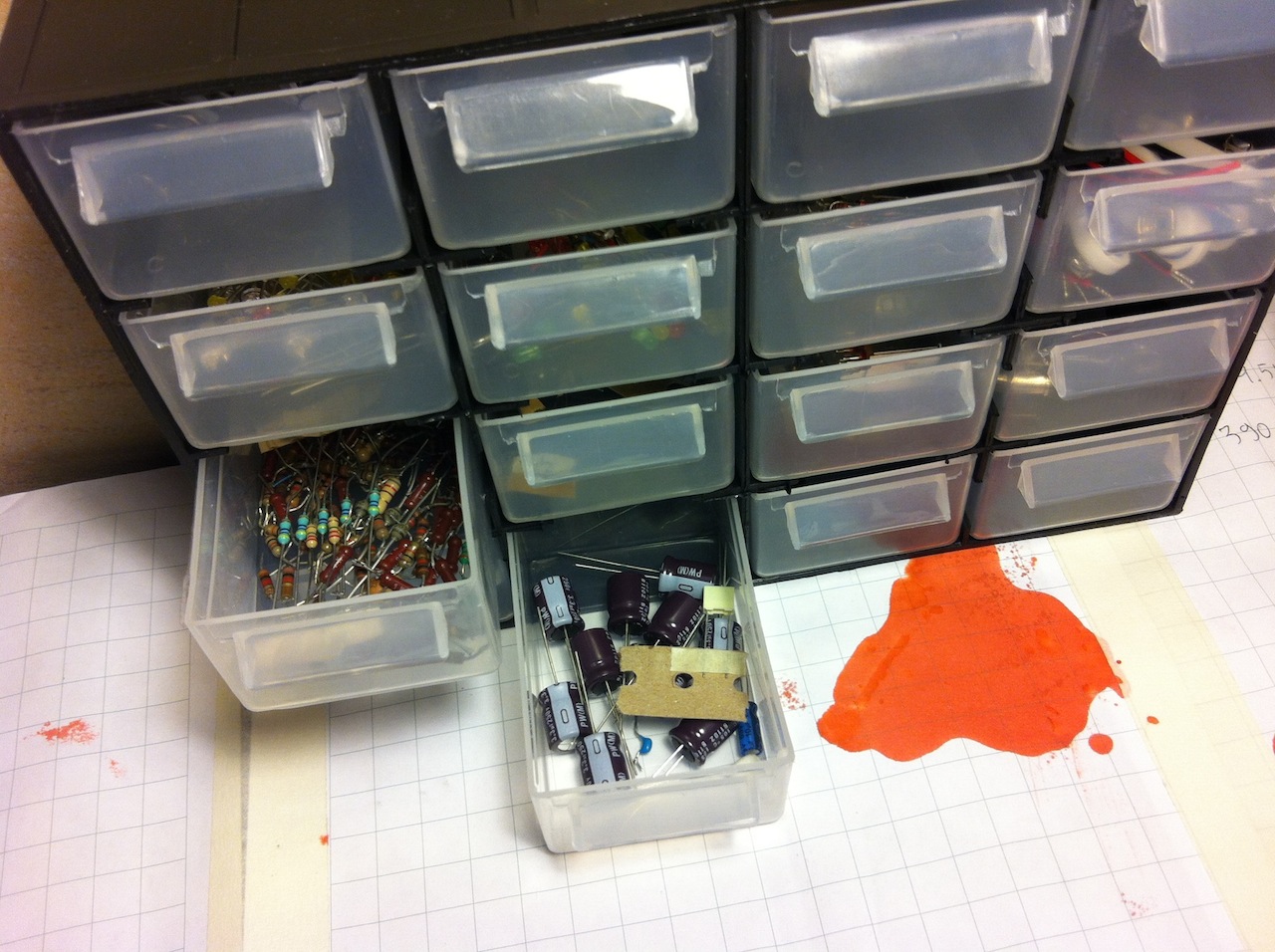
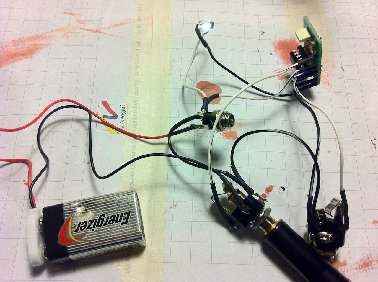
Here are the parts and components:
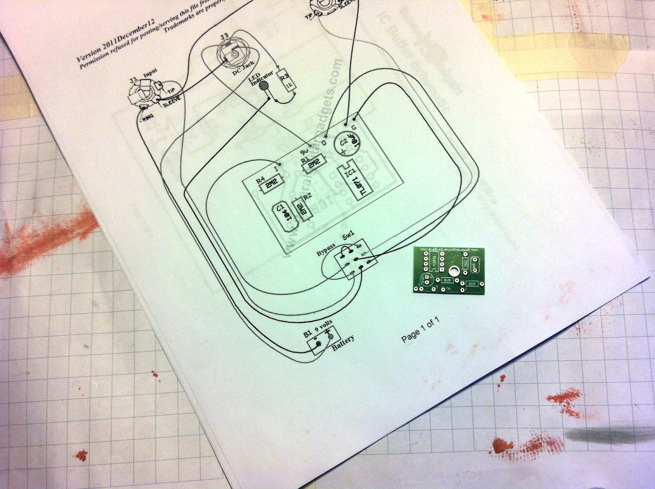
- PCB -> I got the circuit board from General Guitar Gadgets for about €5 (plus international shipping, makes about €8)
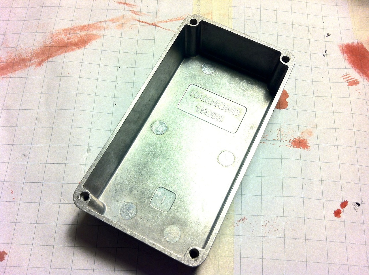
- Hammond 1590B aluminum enclosure
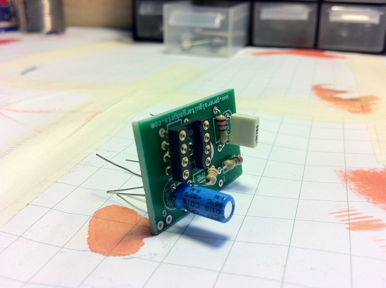
- TL071 OpAmp
- 3x 2.2MΩ resistors
- 1x 0.10uF capacitor
- 1x 10uF capacitor
- 1x IC DIP8 socket
- 2x stereo jack socket
- 1x 9V battery clip
- 1x 9V DC 2.1mm socket
- 1x golden white LED
- 1x 1KΩ resistor
- 1x 33KΩ resistor (values between 5KΩ and 1MΩ are suitable as well)
- some wires
- some heat shrink tube
Total with shipping (I got the components from an online store): about €25 total.
Here are the tools:
- soldering iron, lead, sponge for cleaning the iron tip…
- pliers, wire cutter, screwdriver…
- some powertools to drill holes…
- some patience
- and whatever else you might need to get the job done
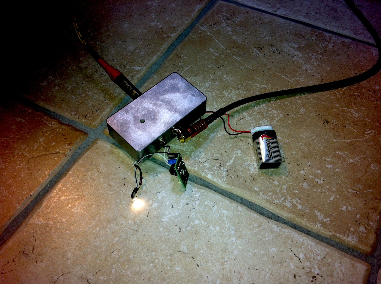
Here we go
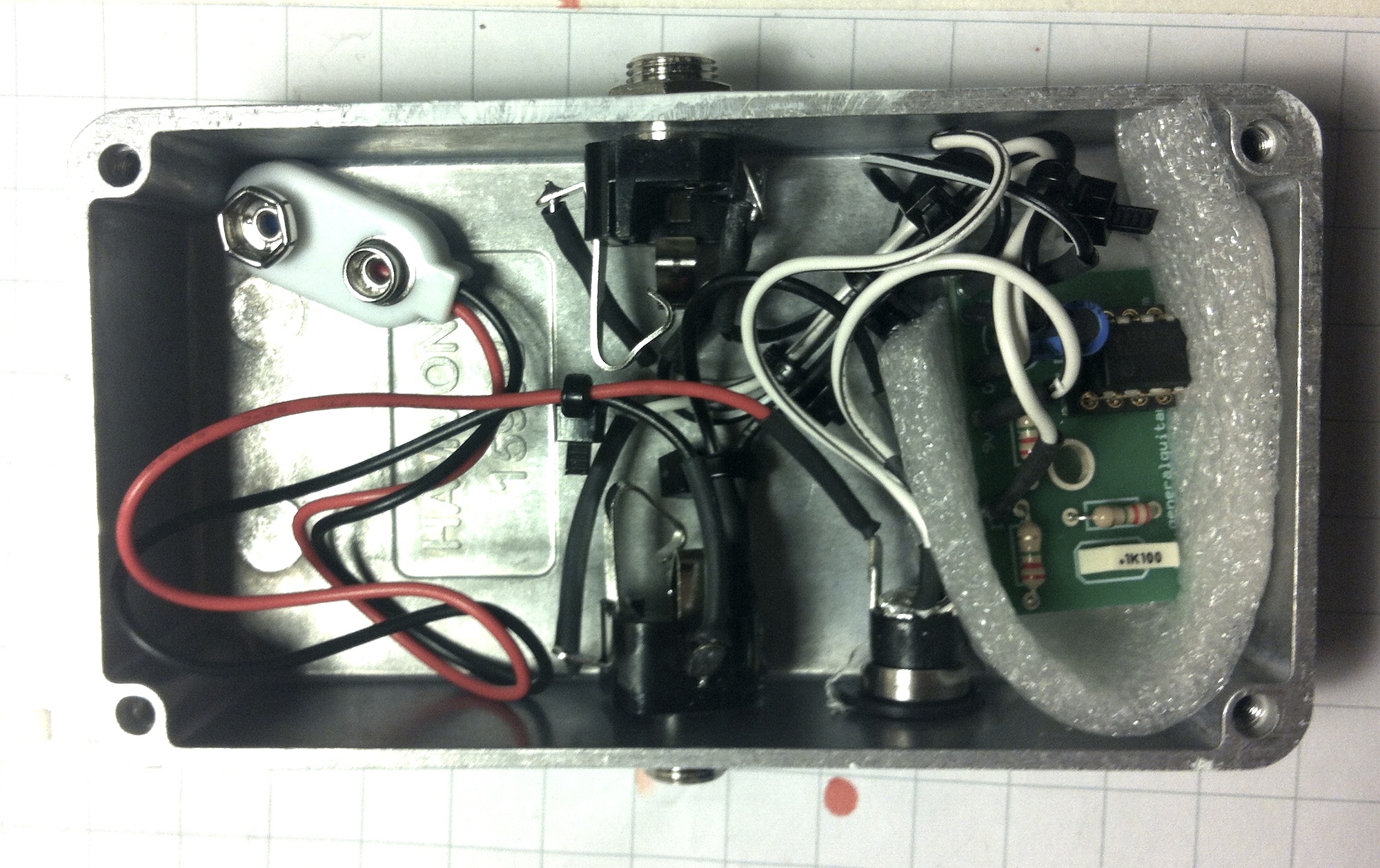
I downloaded the instructions from GeneralGuitarGadgets.com website. The only big difference between the original circuit and the one I built is I omitted the 3PDT footswitch. There is no reason whatsoever to remove the buffer from the pedal chain.
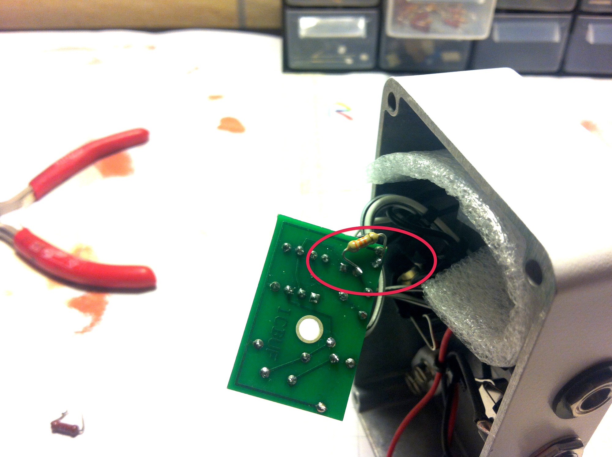
I also added an output pull-down resistor to avoid pop sounds (more details at the end of the page. Yes, you have to scroll down and actually read text not just watch images).
(click on each image to enlarge)
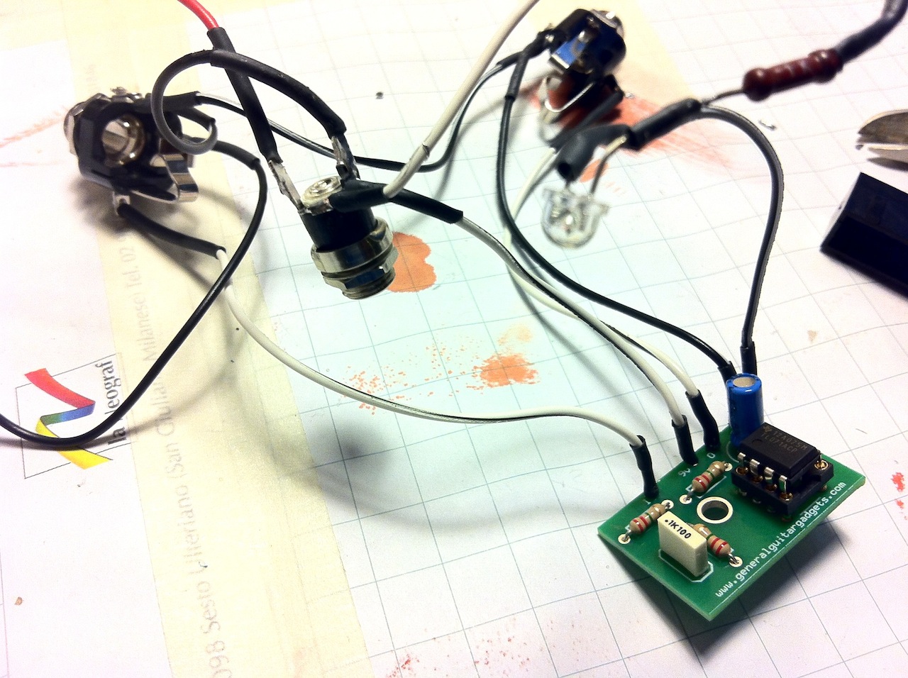
After plugging the buffer into my pedalboard I found out a loud pop occurred when I engaged a true bypass distortion pedal which comes right after the buffer pedal. After some research on the internet I found out there was some DC leaking through the output capacitor into the output jack of the buffer.
I solved this by soldering a 33KΩ resistor from the negative tip of the capacitor to the ground connector (pulldown resistor). Basically any value between 5KΩ and 1MΩ is ok. Low resistor values are good at eliminating pop sounds, but too low values can affect the tone as well. Trial and error, as there is no “perfect” value.
Improvements after this article has been written:
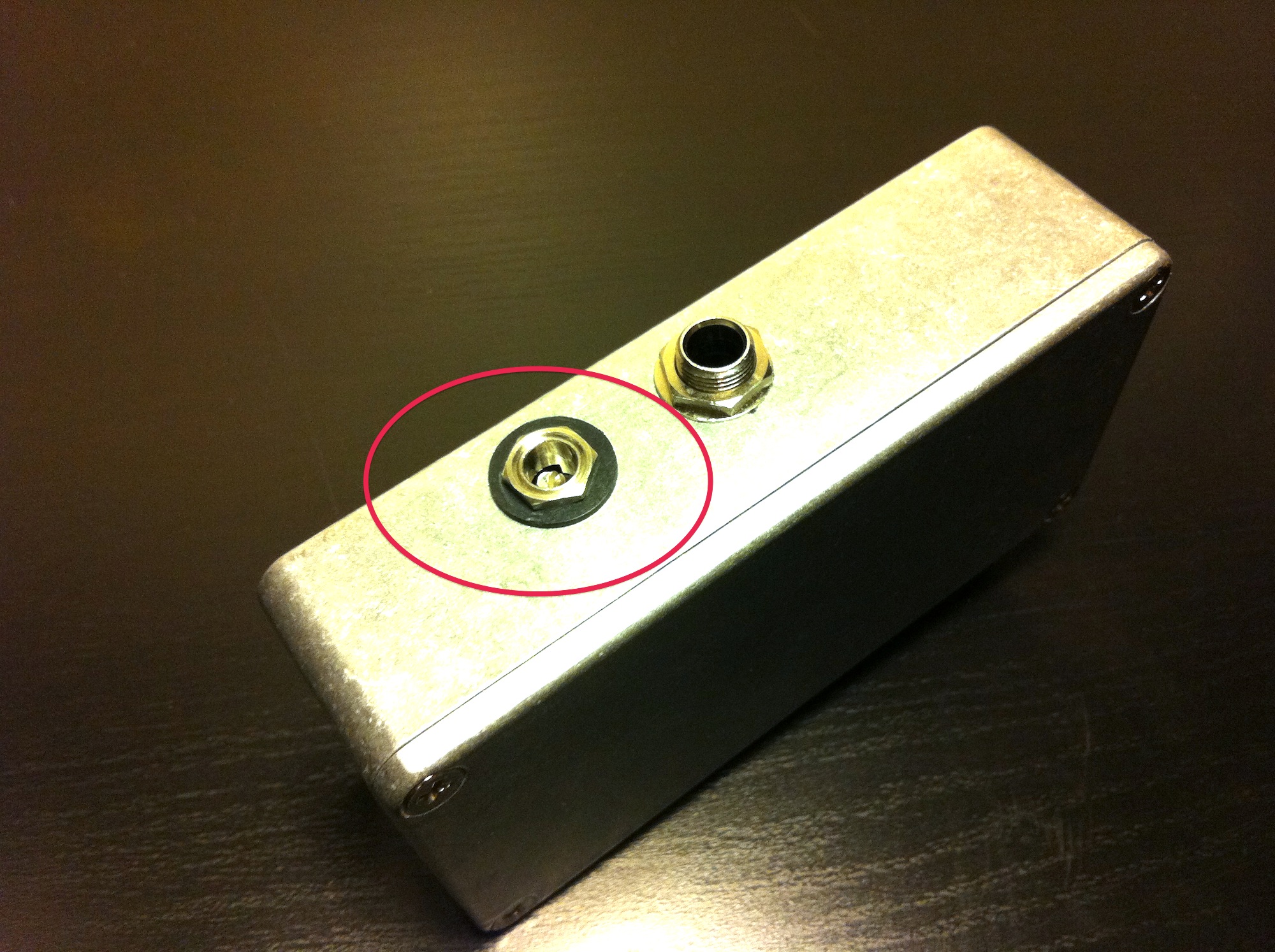
- I replaced the metal DC plug with an isolated plug
- Removed the battery clip and put the circuit in a smaller aluminum enclosure, saving some pedalboard real estate
* = further readings:
Posted on July 13th 2012 July 13th 2012