Crybaby is known for sucking tone when bypassed. At a certain point, Dunlop added an input buffer to address the tone sucking issue.
Since I built a buffer pedal myself, I guess it’s time to remove the Crybaby input buffer and perhaps convert it to true bypass switching. If you dare handling a soldering iron and burn your fingertips, then it’s quite an easy process.
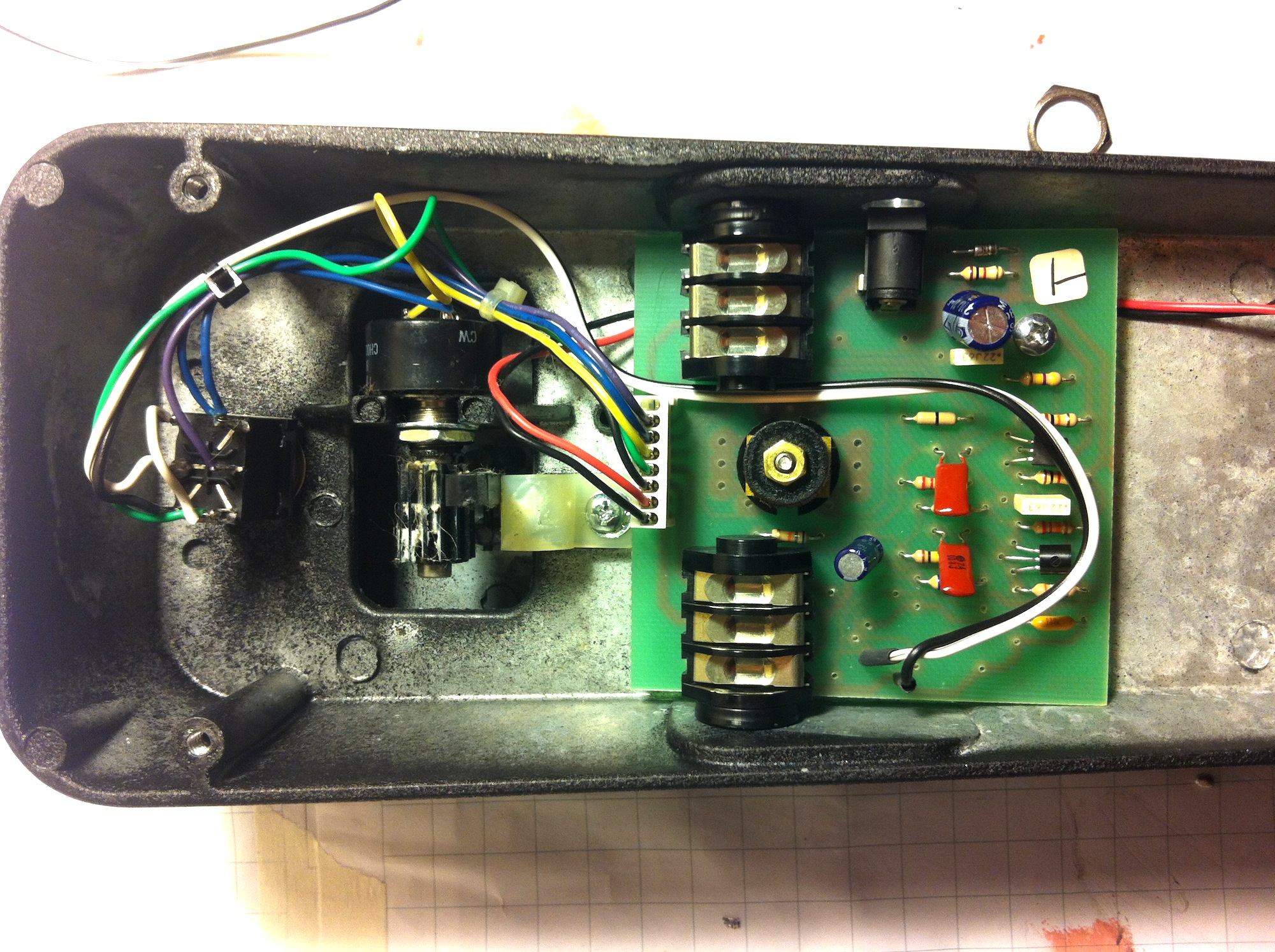
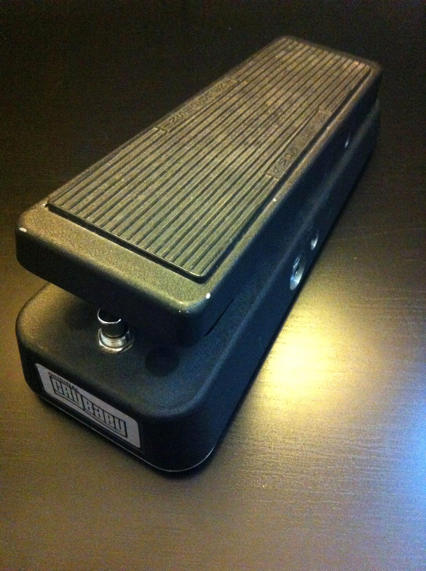
You need to get yourself a DPDT or a 3PDT foot-switch, and some wire. The following instruction should be valid for Dunlop Crybaby GCB-95 rev F and later. The wah pedals pictured here are rev G (DPDT) and rev H (3PDT).

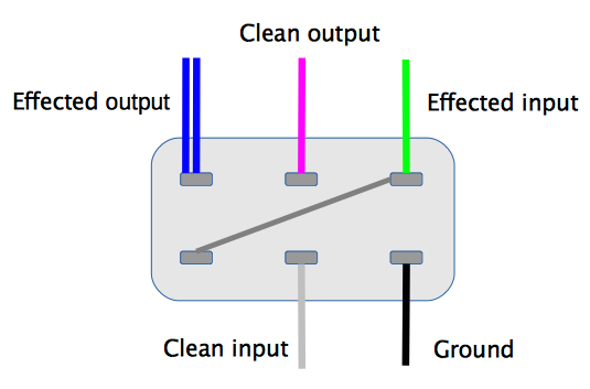
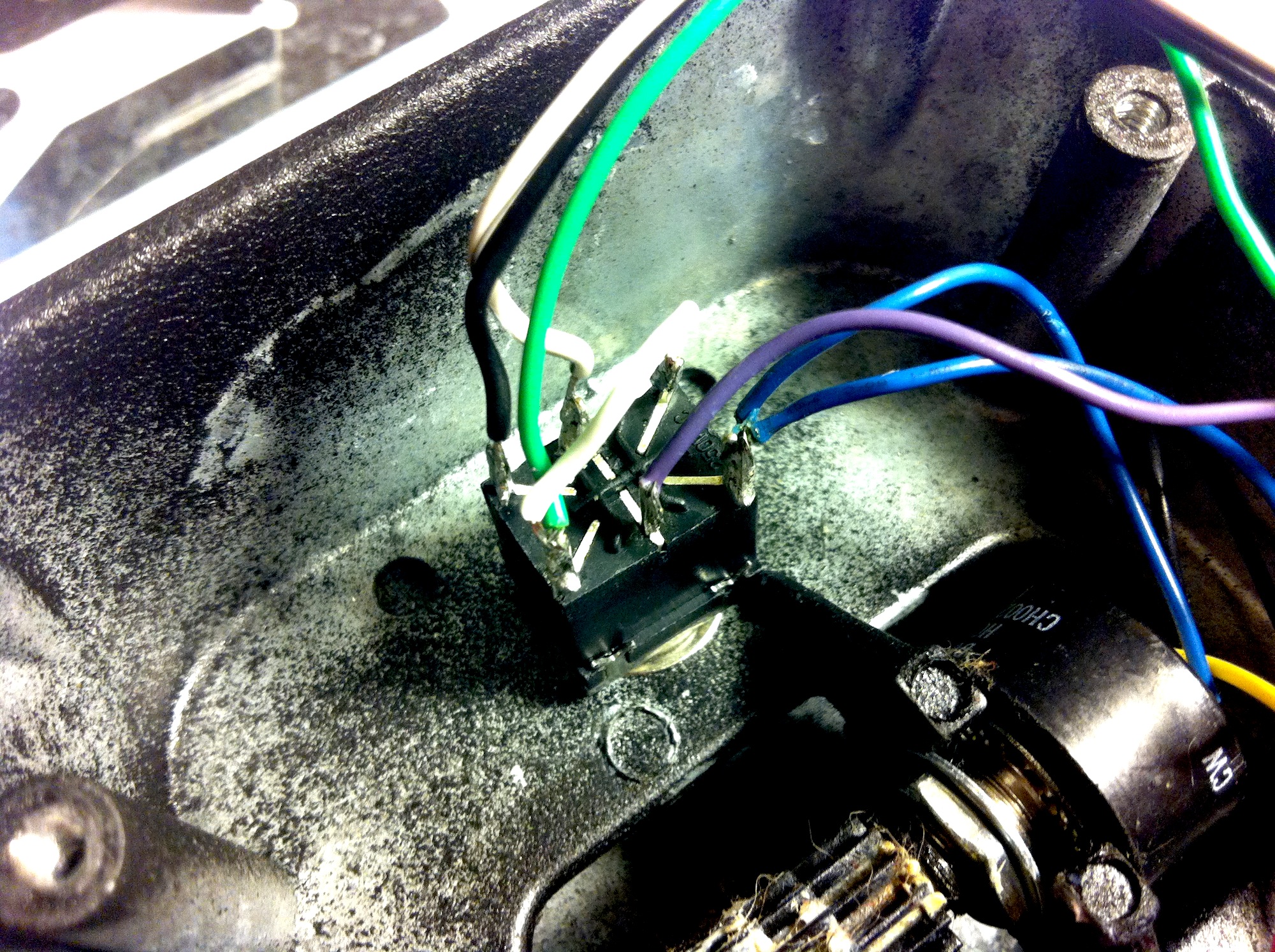
True bypass mod: DPDT switch and no LED
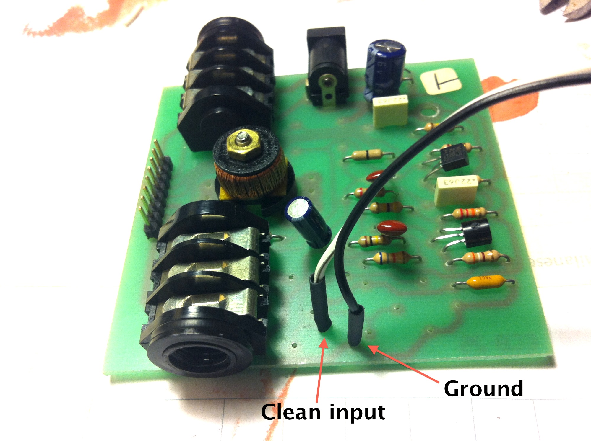
This is the easiest and reversible mod. Start by remove all the wires from the stock switch. For 3PDT and LED mod, scroll down.
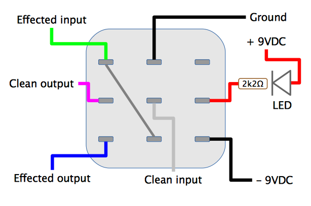
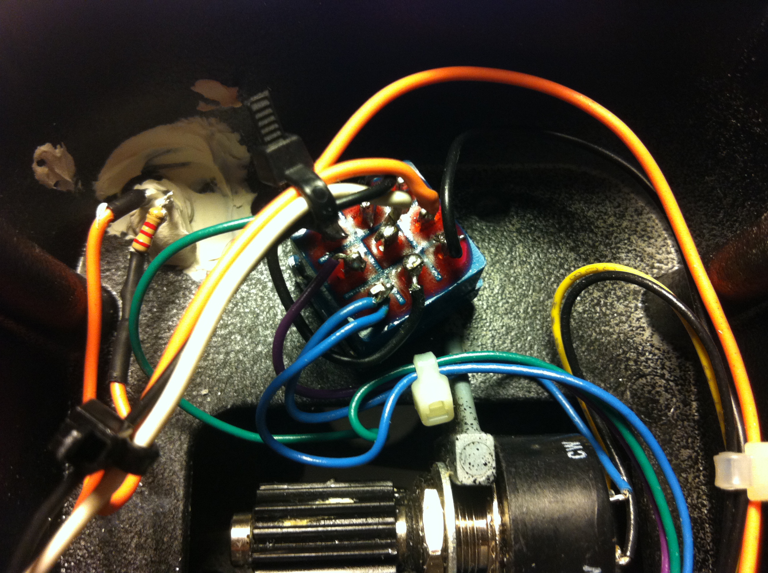
True bypass mod: 3PDT switch and LED
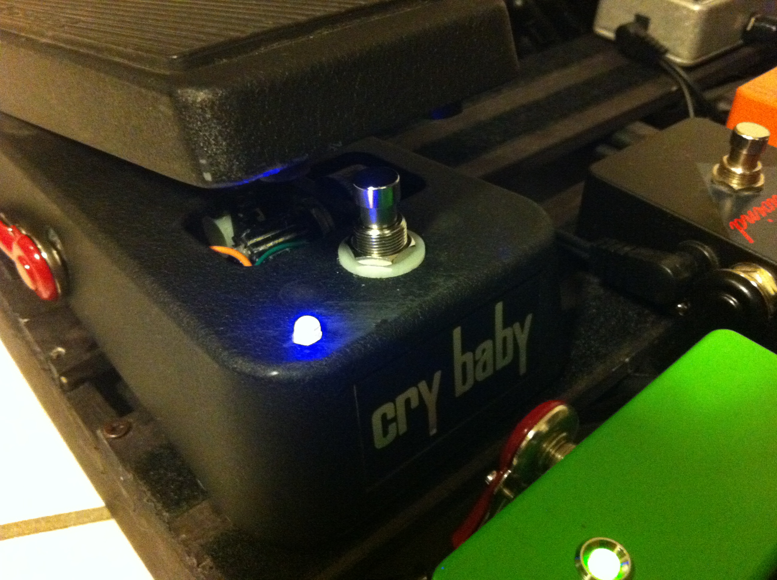
If you like, you can use a 3PDT footswitch and maybe add an LED to show when the pedal is engaged. This requires more work and you need to drill a hole in the metal case. Please notice that the case is a quite hard metal – at least for my HSS drill bits. I like to use a Dremel power tool with variable speed for these jobs.
You also need to get 9VDC from the PCB in order to power the LED. Not too complicated, see below for details.
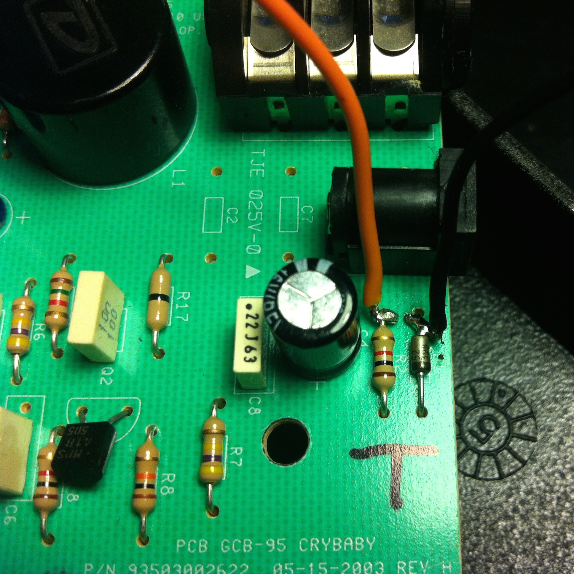
The LED needs a resistor. I used a 2,2K Ω value, but you can use anything between 1K and 10K. The lower the value, the brighter the LED (brightness may also vary from LED to LED).
Solder the resistor to the switch as shown below, then to the LED’s cathode (short leg). After that, solder the positive power wire coming from the PCB to the anode (long leg, also marked by the LED straight side). Then solder the negative power wire to the 3PDT switch as shown below.

Posted on August 5th 2014 August 5th 2014